Zilog eZ8 development
Tutorials, Programmers Reference, Tools, Schematics
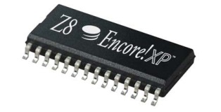
Welcome to our sourceforge project. Our goal is to introduce the Zilog Z8 encore! XP microcontrollers to the homebrew electronics community. Tinkerers, makers and students should know about these capable chips.
The eZ8 microcontroller is a good platform for people who want to get into low level programming.
Get started
To get started please visit our Tutorial.
Programmers Reference
For further reference and documentation please go to the Programmers Reference where we post new articles weekly.
There is also a Hardware Reference which gives more in-depth information about devboards and device specifications.
Chat with other users
Check out our IRC chat #zilog at EFnet.
eZ8 OS
An operating system for the eZ8 microcontrollers. Read more
Please submit corrections, suggestions, and new documentation here: Submit a ticket
This is not an official Zilog website. Zilog nor 8times8 are liable for any damage done to equipment. Tutorial and reference copyright ©8times8 Creative Commons CC-0 License (public domain.) This reference uses content from Zilog's technical datasheets. Fair use only. Datasheets copyright © 2013 Zilog®, Inc. Z8, Z8 Encore!, Z8 Encore! XP and Z8 Encore! MC are trademarks or registered trademarks of Zilog, Inc. Read Zilog's terms at zilog.com
Website design by Koen van Vliet. Hosted by sourceforge.net